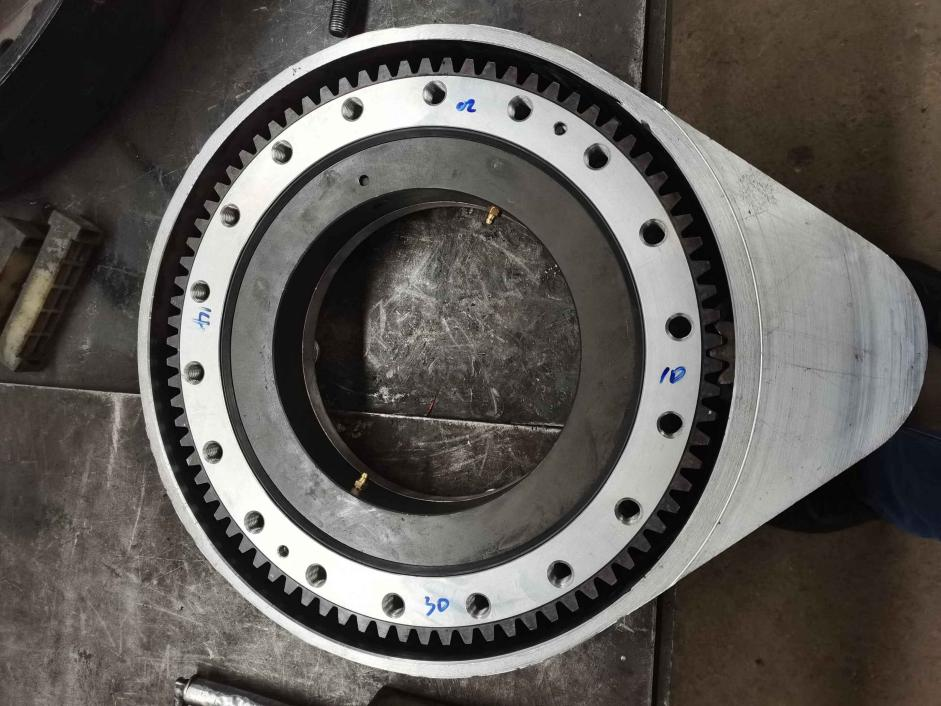
Gear-type slewing drive is often referred to as straight-tooth slewing drive. The transmission principle is a reduction device that drives the ring gear of the slewing support to rotate through a pinion. It is easy to draw a conclusion from the transmission principle. The straight-tooth slewing drive cannot be self-locking. If you want to achieve exact stop, you must use a braking device to lock it.
The following are five straight-tooth rotary drive locking methods:
1. Straight tooth slewing drive driven by a servo motor, under the condition of small inertia, the spur gear start locking is usually achieved by the servo motor quasi-stop. The locking force of the servo motor is driven by a planetary reducer and a straight tooth slewing drive. The reduction ratio is enlarged, and finally reflected on the turntable. The final locking force on the turntable is still very large, which is very suitable for working conditions with small inertia.
Straight-tooth rotary drive using a hydraulic motor. In use, the hydraulic motor can be braked to achieve the locking of the straight-tooth drive. There are usually 3 hydraulic motor braking methods:
Braking with accumulator: Install accumulators near the oil inlet and outlet of the hydraulic motor to achieve bidirectional braking on the hydraulic motor.
Braking with normally closed brake: When the hydraulic oil in the brake cylinder loses pressure, the brake will act immediately to achieve braking.
3. Use the straight-tooth rotary drive of the brake decelerating motor, and the disc brake of the brake motor is installed on the end cover of the non-output end of the motor. When the brake motor is connected to the power source, the electromagnet attracts the armature, the brake armature is separated from the brake disc, and the motor rotates. When the brake motor loses power, the electromagnet cannot attract the armature, and the brake armature contacts the brake disc, and the motor immediately stops rotating. The purpose of the straight-tooth rotary drive lock is realized through the characteristics of the brake motor’s power-off braking.
4. Design pin holes on the rotating ferrule on the straight-tooth rotary drive. For the straight-tooth drive that needs to be locked at a fixed position, we can design the pin hole on the rotating ferrule when designing, and design it on the frame Pneumatic or hydraulic bolt mechanism, when the straight tooth drive rotates, the bolt mechanism pulls out the pin, and the straight tooth drive can rotate freely; reaching the fixed position that needs to be stopped, the bolt mechanism inserts the pin into the bolt hole, and the straight tooth drives the rotating sleeve The ring is fixed on the frame and cannot be rotated.
5. Independent braking gear on spur drive. For application cases that require frequent braking and large braking force, the above braking method can no longer meet the requirements of use. Large braking force will cause gears, reducers, and motors. Failure of the connection between the two will cause premature damage to the reducer. For this, a straight-tooth drive with an independent brake gear is designed, and a separate brake gear is designed to be responsible for the braking of the straight-tooth drive to achieve independent braking, avoid transmission connection failure, and avoid damage to the reducer or motor.
Post time: Dec-01-2021