
|
Application situation |
fs |
fL |
On principle, the static maximum load that the slewing bearing support must be used as a computation value, which must include additional load and test load.
Not included in the application in the table, the static safety factor fs can be selected by reference to the similar working conditions and applications in the table. Mf=Reverse overturning moment on empty load M= The overturning moment of maximum amplitude is used for the application static safety coefficient fs to take 1.45, because of the high average load and heavy working conditions, it is preferable to choose the multi-row rolling slewing bearing. |
|||
| Floating crane (cargo) |
1.10 |
1.0 |
||||
| Mobile crane (cargo) | ||||||
| Marine deck crane | ||||||
| welding equipment | ||||||
| Table (continuous operation) | ||||||
|
Tower crane |
* Rotation at top |
Mf≤0.5M |
1.25 |
1.0 |
||
| 0.5M≤Mf≤0.8M |
1.15 |
|||||
| Mf≥0.8M |
1.25 |
|||||
|
rotation at base |
1.0 |
|||||
| Rotation crane (cargo load) |
1.15 |
|||||
| Shipping crane | ||||||
| l ship Loader/unloader | ||||||
| Metallurgical overweight machine |
1.45** |
1.5 |
||||
| Mobile crane (grab or handle heavy work) |
1.7 |
|||||
| Rotation crane (grab or sucker) | ||||||
| Bridge crane (grab or sucker) | ||||||
| Floating crane (grab or sucker) | ||||||
|
2.15 |
|||||
| Stacker-reclaimer | ||||||
| Cantilevered conveyor | ||||||
| Offshore overweight machine |
Special standard |
In these applications, the working conditions vary considerably, such as the rotary support used for the non-regular rotation, only the static check. For the rotary support used in continuous rotation and intermittent rotation, dynamic life calculation is required. | ||||
| Railway crane |
1.00 |
|||||
| Deck crane (cargo load) | ||||||
| Stacker |
1.10 |
|||||
| Delivery wagon | ||||||
| Rope excavator/cable bucket |
1.25 |
|||||
| Less than or equal to 1.5 M3 hydraulic excavator |
1.45 |
|||||
| More than 1.5 M3 hydraulic excavator |
Special standard |
|||||
| ladle turret |
1.75 |
|||||
Note: fL is the dynamic safety factor. It must be used in combination with dynamic load curve. It comes from experience and experimentation. It is a reference value based on maximum working load.
For example:The portal crane diagram
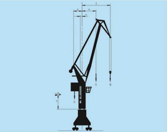
The calculation method of maximum load is recommended as follows:
Before choosing the rotary support, the static safety factor fs that should be considered for the host should be determined, which can be found in schedule 1. Portal crane:fs=1.45
When the maximum static load is known, the calculation formula of its load is as follows:
1) the maximum working load of an eight-level wind force
axial force Fa = Q + A + O + G
overturning moment M = Q × lmax + A × amax + W × r – O × o – G × g
2)Regardless of wind force, consider the load of 25% test load
axial force Fa = 1.25 × Q + A + O + G
overturning moment M = 1.25 × Q × lmax + A × amax – O × o – G ×
Example: the working load and amplitude of a clamshell port are known as follows:
Q = 260 kN lmax = 23 m 1max=23m
A = 75 kN amax = 11 m amax=11m
O = 450 kN o = 0.75 m o=0.75m
G = 900 kN g = 3 m g=3m
W = 27 kN r = 6.5 m1) r=6.5m
Maximum working load of wind power at level 8
Fa = Q + A + O + G
=260 + 75 + 450 + 900
=1685 kN
M = Q×lmax + A×amax + W×r – O × o – G× g
=260 × 23 + 75 × 11 + 27 ×6.5×450 ×0.75×900 × 3
= 3943 kNm
2) regardless of wind force, consider the maximum working load of 25% test load
Fa = 1.25×Q + A + O + G
=325 +75 +450 +900
= 1750kN
M = 1.25×Q×lmax + A×amax – O×o – G×g
= 325 × 23 + 75 × 11×45 × 0.75×900 × 3
= 5566.3 kNm
3)maximum working load regardless of wind force
Fa = 1685 kN
M = Q×lmax + A×amax – O×o – G×g
= 260 × 23 + 75 × 11×450 × 0.75×900 × 3
= 3767.5 kNm
Load condition 2 is used as the working load of static calculation
According to schedule 1, the portal crane (grab bucket) should be supported by three rows of roller-type rotary support:
The static reference load of rotary support is:
Fa' = 1750 kN × 1.45 = 2537.5 kN M'= 5566.3 kNm × 1.45 = 8071.1 kNm
The calculation load of bolt is:
Fa = 1750 kN M = 5566.3 kNm
According to the above calculation results, the selection of the bearing capacity curve can be determined to select the rotary support of 13*.45.2000.002
The above description is the detailed calculation method of slewing bearing size. According to the calculation results, you can choose the suitable slewing bearing model in our product catalog. If you don’t know how to calculate, please feel free to contact us by email. We will serve you wholeheartedly!
Post time: Apr-08-2021